 AI
AIPolymerization Shrinkage of 3D Resins: How to Manage It in the CAD Workflow
Polymerization shrinkage is the main factor causing inaccuracy in dental 3D printing resins. Here's how to compensate for it in the CAD workflow and achieve sub-millimetric fits.
TL;DR
Photopolymerizable resins shrink between 0.5% and 4% during polymerization. Without compensation in the CAD file or print profile, the finished restoration will be smaller than designed, leading to marginal gaps and occlusal interferences. The solution is a calibrated scaling factor for each resin, combined with controlled post-curing parameters.
Polymerization shrinkage is the silent main enemy of precision in dental 3D printing. Every photopolymerizable resin shrinks as monomers bond into polymer chains—and that shrinkage, if not anticipated and compensated for, results in marginal gaps, occlusal interferences, and restorations that don't fit.
The good news: the phenomenon is physically predictable, measurable, and—with the correct workflow—almost entirely neutralizable. Let's see how.
What Really Happens During Photopolymerization
When UV light (typically 385–405 nm) hits a resin layer, it initiates a chain reaction: photoinitiators generate free radicals that link monomers, forming three-dimensional polymer networks. The conversion from monomer to polymer always involves molecules moving closer together—and thus a reduction in volume.
The extent of shrinkage depends on three main factors:
- Monomer type: monomethacrylates shrink more than dimethacrylates; urethane-dimethacrylate (UDMA) or bisphenol-A glycidyl methacrylate (Bis-GMA) based formulations show different shrinkage
- Degree of conversion: the higher the conversion (% of reacted double bonds), the greater the shrinkage—but also the higher the final mechanical stability
- Presence of inorganic fillers: highly filled resins (like CAD/CAM composites) shrink less because the monomer fraction is reduced
According to a study published in Dental Materials (Saleh et al., 2022), dental 3D printing resins show volumetric shrinkage ranging between 0.5% and 4.2% depending on the formulation, with typical values for model resins around 1–1.5% and provisional resins up to 3%.
Volumetric shrinkage and linear shrinkage are not the same thing. A volumetric shrinkage of 3% corresponds to a linear shrinkage of approximately 1% in each direction (³√0.97 ≈ 0.99). For marginal adaptations where you work with tolerances of 50–120 µm, even a linear error of 1% on a 12 mm crown means 120 µm of deviation—already at the limit of clinical acceptability.
Where the Problem Manifests: The Three Critical Points
Not all shrinkage creates the same type of problem. It depends on where and at what stage it occurs.
1. Shrinkage During Printing (Layer-by-Layer) Each layer polymerizes while the previous one has already solidified. Differential shrinkage between layers can generate internal stresses that accumulate and are released as overall geometric distortion—especially in long geometries (Toronto Bridge, full-arch prostheses).
2. Shrinkage During Post-Curing Polymerization in the UV chamber completes the reaction initiated by the printer. This step adds further shrinkage—more uniform than intra-layer shrinkage, but still significant. The temperature of the post-curing chamber directly affects this: higher temperatures accelerate conversion but also increase shrinkage.
3. Anisotropic Shrinkage In complex geometries, shrinkage is not isotropic. The Z-axis (printing direction) behaves differently from the X and Y axes because each layer is constrained by the previously hardened layer. This generates predictable distortions that vary with the slicing software and the positioning of the part on the build plate.
How to Compensate: The Three-Tiered Strategy
Managing shrinkage is not a single operation, but a layered strategy that acts at three points in the workflow.
Level 1 — Scale Factor in the CAD File or Slicer
The most immediate method is to apply a magnification factor to the file before printing, so that the finished part, after shrinking, reaches the nominal dimensions of the CAD design.
The factor must be empirically calibrated for each resin + printer + post-curing parameter combination. The standard protocol involves:
- Printing a calibration cube (e.g., 20×20×20 mm) with the target resin
- Measuring the actual dimensions with a digital micrometer after complete post-curing
- Calculating the factor:
F = nominal_dimension / actual_dimension - Entering the factor on the X, Y, and Z axes (separately, if shrinkage is anisotropic)
A typical example: for a provisional resin, the linear compensation factor can be 1.008 on the X/Y axis and 1.012 on the Z axis. A difference of just 4 thousandths between the two axes — but enough to cause systematic marginal errors if only one isotropic factor is used.
Level 2 — Compensatory Design in the CAD File
Some geometries are structurally more vulnerable to distortion. In the CAD file, the problem can be anticipated with targeted design choices:
- Slightly oversized margins (10–20 µm) in provisional crowns, which shrinkage will bring to the target measurement
- Symmetrical geometries where possible, to evenly distribute internal stresses
- Print supports positioned to constrain critical areas (marginal areas, connectors) during polymerization, limiting distortion
Level 3 — Strict Post-Curing Control
Post-curing is the most often overlooked parameter, yet it has a direct impact on residual shrinkage. The variables to standardize are:
| Parameter | Impact on shrinkage | Recommendation |
|---|---|---|
| UV exposure time | More time → more conversion → more shrinkage | Follow manufacturer's technical data sheet |
| Chamber temperature | Warmer → faster and more complete reaction | 40–60°C typical; do not exceed indications |
| Part rotation | Uniform exposure = more isotropic shrinkage | Continuous rotation, not static |
| Pre-cure washing | Unpolymerized resin residues alter geometry | IPA or dedicated solvent, precise time |
Extending post-curing beyond the indicated times does not improve mechanical properties — it often worsens them due to material embrittlement — and increases residual shrinkage. Each resin has a conversion curve with a plateau: beyond that point, stress is added without gaining strength. Always adhere to the manufacturer's technical data sheet certified according to ISO 10993 and MDR 2017/745.
Resin Comparison: Shrinkage and Clinical Application
Not all resins used in dentistry behave in the same way. This table summarizes typical shrinkage values and practical implications for the main categories.
| Resin Type | Typical linear shrinkage | Main application | Compensation needed |
|---|---|---|---|
| Model resin (high precision) | 0.4–0.8% | Study models, dies | Low — fixed factor often sufficient |
| Provisional resin (PMMA-based) | 0.8–1.5% | Temporary crowns and bridges | Medium — batch calibration |
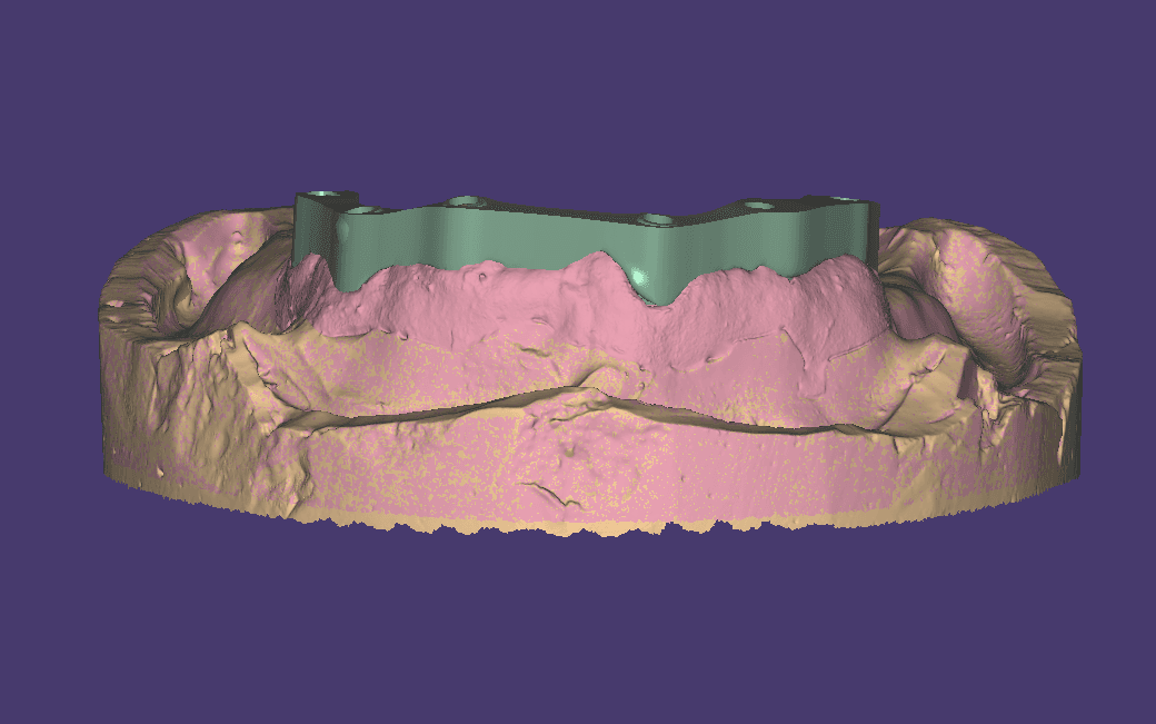
| Surgical guide resin | 0.5–1.0% | Implant guides | Medium — critical for guide holes |
| Denture base resin | 1.0–2.0% | Removable bases | High — anisotropic distortion frequent |
| Splint/bite guard resin | 0.6–1.2% | Night guards, splints | Medium — uniform thickness helps |
(Values aggregated from literature: Alharbi et al., Journal of Prosthetic Dentistry, 2023; Revilla-León et al., International Journal of Prosthodontics, 2022)
The Case of Surgical Guides: Where Shrinkage is Most Critical
While a 100 µm error in a provisional is clinically manageable, the same inaccuracy in a surgical guide can result in an angular deviation of 1–2° on the implant — with consequences that propagate throughout the prosthetic chain.
The diameter of the guide holes in a printed guide is designed for a specific metal sleeve (typically 5 mm outer diameter). An uncompensated shrinkage of 1% on that diameter means 50 µm less — which can make the sleeve too tight or, worse, cause it to fit loosely if shrinkage is greater than expected.
According to a study published in Clinical Oral Implants Research (D'haese et al., 2023), the average accuracy of surgical guides produced with precision DLP printers and certified resins is 0.8 mm of apical deviation, but this figure is highly dependent on the correctness of shrinkage compensation and the post-curing protocol.
For surgical guides, it is good practice to systematically use a post-print dimensional verification protocol with a digital caliper on critical points (guide hole diameter, saddle width) before each delivery. This is not an optional procedure: it is part of the quality workflow.
Visualization: Linear Shrinkage by Resin Category
The Role of Slicing Software in Shrinkage Management
Modern slicing software incorporates shrinkage compensation functions that act directly on the file before print path generation. However, the quality of this compensation varies greatly:
- Isotropic compensation: applies the same factor on all three axes. Quick and sufficient for simple geometries (models, flat splints)
- Anisotropic compensation: different factors for Z compared to X/Y. Necessary for tall geometries (anterior crowns, full-arch structures)
- Material profiles: some software allows saving compensation profiles for specific resins, ensuring consistency across different batches
The problem is that preset profiles provided by printer manufacturers are often optimized for their own brand resins. When using third-party resins — even MDR-certified ones — manual recalibration of the profile is almost always necessary.
How to Structure a Validation Protocol in the Lab
A laboratory that wants to manage shrinkage systematically — and not empirically — must build a documented validation protocol. These are the minimum steps:
- Calibration sample for each new resin or new batch: a simple geometric specimen with known dimensions on all three axes
- Post-cure measurement with a calibrated instrument (digital micrometer, structured light scanner preferred for complex geometries)
- Calculation and recording of the factor for that resin/printer/parameter combination
- Verification on a clinical part before production: a sample crown on a calibrated die, with marginal gap measurement using an optical microscope or SEM
- Protocol update with each change of resin batch (shrinkage can vary even between batches from the same manufacturer)
This type of protocol is also an implicit requirement in the quality management demanded by MDR 2017/745 for custom medical devices: traceability of the production process includes documentation of printing and post-cure parameters.
Frequently Asked Questions
Does polymerization shrinkage change with different resin batches?
Yes. Even between batches from the same manufacturer, variations in chemical formulation can alter shrinkage behavior. For high-volume production or critical applications (surgical guides, definitive restorations), it is good practice to revalidate the compensation factor with each batch change.
Is it sufficient to use the manufacturer's scaling factor?
Often no. The factor indicated by the manufacturer is typically derived using their own printer and post-cure parameters. On your machine, with your UV chamber and your washing times, the behavior may be different. The manufacturer's factor is a starting point, not a definitive datum.
How does ambient temperature affect shrinkage?
Laboratory temperature variations affect resin viscosity before printing and reaction speed during post-curing. Environments at 20–22°C with controlled humidity ensure more repeatable results. In laboratories with significant temperature fluctuations, the variability between morning and afternoon prints can be measurable.
Does shrinkage add to sintering shrinkage for zirconia?
No: for zirconia, we speak of sintering shrinkage (typically 20–25% linear), which is compensated with a different magnification factor in the CAD file. The two phenomena concern completely separate materials and processes and do not add up.
Is there a limit beyond which shrinkage is no longer compensable?
Theoretically no — any uniform linear shrinkage is compensable with a scaling factor. The real problem is non-uniform shrinkage: complex geometries, large thickness differences in the same structure, or problematic print orientations generate local distortions that a simple global factor cannot correct. In these cases, the solution is to adjust the part placement on the slicing and the supports.
Conclusions and Next Steps
Polymerization shrinkage is not a problem to be accepted as inevitable: it is a known, measurable, and controllable physical phenomenon with a structured workflow. Laboratories that manage 3D production professionally — with batch calibration, standardized post-cure parameters, and systematic dimensional verification — achieve marginal adaptations in line with clinically acceptable values even for temporary resins and surgical guides.
If you are outsourcing 3D production or CAD design, ensure your partner has documented protocols for shrinkage management — and ask to see them. Dentra handles the design: you receive the file within 24 business hours, ready for printing in your lab or a partner lab, and the order status is always visible.
Owner and Technical Director — Dentra
Second-generation dental technician, specialised in dental CAD/CAM, 5-axis milling and Toronto Bridge design. Leading the digital transformation of Dentra since 2017.