 AI
AIMultiple Scanning and STL Superimposition: How to Avoid Alignment Errors
When combining multiple intraoral scans or superimposing STL files, alignment errors can compromise the entire design. Here's how to avoid them.
TL;DR
Superimposing multiple STL files from different scans is one of the most critical phases of the digital workflow: even errors of a few tenths of a millimeter in alignment result in prostheses that do not fit. This article explains the main causes, the parameters to check, and the correct workflow to reduce discrepancies to less than 50 µm.
Misaligning two scans is one of the most silent errors in the digital workflow: you don't see it until the prosthesis is already milled and doesn't fit. By then, the damage—in terms of material, time, and credibility with the client—is already done.
Yet, in most cases, the error doesn't originate from the scan itself, but from how the files are registered and superimposed downstream. Understanding where the chain breaks is the first step to eliminating waste.
Why Multiple Scans Are Used (and Where Problems Begin)
In today's CAD workflow, multiple scans are used in at least three distinct scenarios:
- Scan of the upper arch + lower arch + bite in centric relation — three separate files that must coincide in a shared three-dimensional space.
- Intraoral scan combined with physical model scan — frequent when the preparation is acquired with a desktop scanner and the bite with an intraoral one.
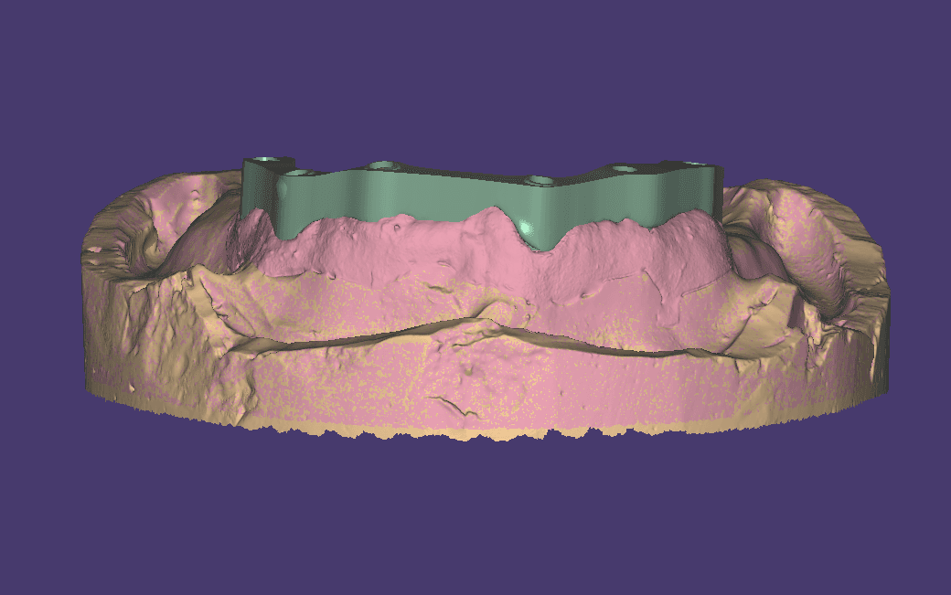
- Integration of implant scans with mucosa scans — crucial in workflows with scan bodies, where the soft tissue file and the implant emergence file must overlap without drift.
In all three cases, the critical error is the same: the alignment software fails to find enough stable reference geometry and "slips" into a mathematically acceptable but clinically incorrect solution.
According to a study published in Dental Materials (2022), the average discrepancy in full-arch scan alignment with automatic (best-fit) alignment varies between 60 and 180 µm in posterior areas, with peaks over 300 µm in the presence of missing teeth or mobile mucosa. For a crown, the clinically acceptable tolerance is 50–120 µm (source: Journal of Prosthetic Dentistry, 2023): the margin of error is almost zero.
The Real Causes of Alignment Errors
1. Insufficient Geometry in the Overlap Area
The automatic (best-fit) alignment algorithm works by finding correspondences between points on the two meshes. If the overlap area is small (for example, only the second molars during bite registration), the alignment plane is unstable, and any small perturbation in the dental geometry—saliva smudges, patient movement, bite registration material artifacts—amplifies the final error.
Rule of thumb: the overlap area must cover at least 4-5 consecutive teeth with well-defined occlusal morphology. Edentulous areas or smooth alveolar ridges do not contribute to alignment; in fact, they destabilize it.
2. Poor Quality Mesh in the Critical Area
An STL file with degenerate triangles, holes in the mesh, or insufficient resolution in the occlusal fossae gives the algorithm poor geometric reference points. The result is an alignment that appears visually correct but has a systematic average deviation of 80–150 µm.
Many CAD software show alignment with a colorimetric heatmap view. Green indicates low deviation, but be careful: the color scale is relative to the maximum deviation present in the file. If the maximum is 500 µm, "green" could still represent 100–150 µm—already beyond the marginal tolerance.
3. Bite Registration with Overly Elastic Material
Low Shore hardness silicone bite registration materials (below 60A) tend to deform during scanning, especially if the patient's arches are still resting. Elastic deformation transmits distorted geometric information: the alignment will be correct relative to the material, not relative to the actual position of the arches in occlusion.
According to a study in Clinical Oral Investigations (2023), self-curing acrylic resin registration materials produce alignment errors that are, on average, 40% lower than conventional silicone bite materials in full-arch situations.
4. Thermal Drift of the Scanner
Intraoral scanners heat up during use. Thermal expansion of optical components introduces a progressive dimensional drift: some measurements on Medit and 3Shape scanners conducted by European university institutes (Universidad Complutense de Madrid, 2023) detected a drift of up to 35 µm for every 10 minutes of continuous use in warm environments. A complete full-arch scan typically takes 8–15 minutes: the accumulated drift becomes significant.
Deviation Map: Where Errors Are Concentrated
The Correct Workflow: Five Checks to Perform Before Sending to CAD
1. Validate Mesh Quality Before Alignment
Before initiating any overlay operation, open the STL file in a mesh viewer (the one built into the CAD software also works) and check:
- Absence of holes in the mesh (hole-free check)
- Number of degenerate triangles — in the occlusal area, it should be <0.1% of the total
- Adequate resolution in the fossae — at least one vertex every 50–80 µm in the reference areas
If the file does not pass these checks, the scan must be repeated. No post-processing can recover missing geometry.
2. Manually Choose the Anchor Area
Do not rely on automatic alignment for multiple full-arch scans. The leading CAD programs for dental labs let you manually define three or more anchor points before launching the automatic refinement alignment. Select points on well-defined cusps, preferably in areas not part of the restoration.
3. Check the Deviation Map Zone by Zone
After automatic alignment, always generate the deviation map and analyze it by sector:
| Zone | Acceptable Deviation | Action if Out of Range |
|---|---|---|
| Restoration area (margin) | < 50 µm | Repeat scan |
| Areas adjacent to restoration | < 80 µm | Verify and document |
| Posterior reference areas | < 120 µm | Acceptable with note |
| Edentulous areas / ridge | < 200 µm | Acceptable for morphology |
| Scan body position | < 30 µm | Repeat if out of range |
4. Verify Centric Relation with Control Scan
For more complex cases (full-arch, Toronto Bridge, extended bridges), always perform a second bite registration with the patient in a seated position and compare it with the first. A discrepancy > 150 µm between the two registrations indicates occlusal instability or technique error: the case must be discussed with the clinician before proceeding to CAD.
5. Document and Archive the Alignment Report
Every STL overlay should generate a numerical report (alignment RMSE, maximum deviation, number of corresponding points) to be attached to the work order. This protects the lab in case of disputes and creates a useful history for improving the process over time.
The RMSE (Root Mean Square Error) parameter of the alignment is the most reliable indicator for evaluating the quality of global alignment. An RMSE < 30 µm for single-arch scans is considered optimal; for full-arch, values < 60 µm are acceptable for most clinical indications. Some CAD software does not directly expose this value: in that case, request it from the vendor or use external mesh analysis software.
Owner and Technical Director — Dentra
Second-generation dental technician, specialised in dental CAD/CAM, 5-axis milling and Toronto Bridge design. Leading the digital transformation of Dentra since 2017.